


How to Install Fittings & Adapters
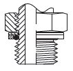
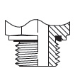
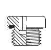
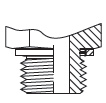
Installation of Non-Adjustable & Straight Port Fittings

- Observe unassembled parts, especially threads and bore to ensure it is free of foreign material, burrs, nicks, etc.
- Make sure compound/material and hardness of O-ring are suitable for the medium type and temperature.
- Observe O-ring for nicks or cuts and replace if any found. Never use a damaged O-ring!
- Install O-ring on male thread and make sure the O-ring is not cocked or twisted. Abut O-ring to the base of the thread.
- Lubricate the O-ring with a light coat of the system’s fluid or suitable lubricant.
- Install retaining ring over the O-ring (if included) and ensure O-ring is seated inside the retaining ring evenly.
- Screw and tighten the fitting or adapter into the port using suggested torque values.
- Inspect the assembly to ensure the O-ring is properly seated and there are no leaks.

Installation of Adjustable Port Fittings
- Following the above steps (Non-Adjustable & Straight Port Fittings) and stop after step 6.
- Back off the adjustable nut and backup washer as far back as possible, ensuring the threads are fully exposed.
- Thread fitting into the port until the seal comes into full contact with the spotface (do not overtighten).
- If installing an elbow, align the direction of the hose or tube end to a desirable orientation by unscrewing the fitting, but be sure not to go past one full turn.
- Utilizing 2 wrenches (one being a torque wrench), hold the fitting in position with one wrench while tightening the adjustable nut with the torque wrench. Use suggested torque values.
- Inspect the assembly to ensure that the O-ring & retaining ring are properly seated, and that there are no leaks.
- If a crowsfoot is used with a torque wrench, adjustments might need to be made to the torque settings otherwise overtightening could occur. Consult your manufacturer for instructions.

BSPP Port – Torque Settings
| Retaining Ring & O-Ring | ED/ES Seal | Bonded Washer | Cutting Face | Banjo | ||||||
|---|---|---|---|---|---|---|---|---|---|---|
 |
 |
 |
 |
 |
 |
 |
 |
|||
| Dash Size | Inch Thread Size-TPI | Straight (Nm) | Adjustable (Nm) | Straight (Nm) | Plugs (Nm) | Straight (Nm) | Straight (Nm) | With Copper Washers | With Soft Seals | |
| Light Series (L) | 02 | 1/8-28 | 18 | 18 | 18 | 13 | 9 | 18 | 18 | 18 |
| 04 | 1/4-19 | 35 | 35 | 35 | 30 | 35 | 35 | 45 | 40 | |
| 06 | 3/8-19 | 70 | 70 | 70 | 60 | 45 | 70 | 70 | 65 | |
| 08 | 1/2-14 | 90 | 110 | 90 | 80 | 65 | 100 | 120 | 90 | |
| 12 | 3/4-14 | 180 | 180 | 180 | 140 | 90 | 180 | 230 | 125 | |
| 16 | 1-11.5 | 310 | 310 | 310 | 200 | 150 | 330 | 320 | ||
| 20 | 1-1/4-11.5 | 450 | 450 | 450 | 400 | 240 | 540 | 540 | ||
| 24 | 1-1/2-11.5 | 540 | 540 | 540 | 450 | 290 | 630 | 700 | ||
| Heavy Series (S) | 02 | 1/8-28 | 25 | |||||||
| 04 | 1/4-19 | 55 | 40 | 35 | 55 | 45 | 40 | |||
| 06 | 3/8-19 | 90 | 80 | 45 | 90 | 70 | 65 | |||
| 08 | 1/2-14 | 110 | 115 | 65 | 130 | 120 | 90 | |||
| 12 | 3/4-14 | 115 | 180 | 90 | 270 | 230 | 125 | |||
| 16 | 1-11.5 | 420 | 310 | 150 | 340 | 320 | ||||
| 20 | 1-1/4-11.5 | 550 | 450 | 240 | 540 | 540 | ||||
| 24 | 1-1/2-11.5 | 600 | 540 | 290 | 700 | 700 | ||||
Please note:
- All torque values are intended for steel fittings.
- For Brass fittings and adapters use 65 % of the torque values.
- For Stainless steel fittings and adapters, use 5% higher value than listed and lubricate threads.
Metric Port – Torque Settings
| Retaining Ring & O-Ring | ED/ES Seal | Bonded Washer | Cutting Face | Banjo | ||||||
|---|---|---|---|---|---|---|---|---|---|---|
|
|
|
|
|
|
|
|
|||
| Dash Size | Inch Thread Size-TPI | Straight (Nm) | Adjustable (Nm) | Straight (Nm) | Plugs (Nm) | Straight (Nm) | Straight (Nm) | With Copper Washers | With Soft Seals | |
| Light Series (L) | 12 | 35 | 35 | 30 | 25 | 25 | 20 | 30 | 45 | 35 |
| 14 | 45 | 45 | 50 | 35 | 35 | 35 | 45 | 55 | 50 | |
| 16 | 55 | 55 | 60 | 50 | 50 | 45 | 65 | 80 | 60 | |
| 18 | 70 | 70 | 80 | 65 | 45 | 55 | 80 | 100 | 80 | |
| 22 | 160 | 180 | 140 | 90 | 60 | 65 | 140 | 140 | 120 | |
| 26 | 250 | 180 | 200 | 135 | 90 | 190 | 320 | 130 | ||
| 27 | 100 | |||||||||
| 33 | 310 | 310 | 380 | 225 | 160 | 150 | 340 | 360 | ||
| 42 | 450 | 450 | 500 | 360 | 210 | 240 | 500 | 540 | ||
| 48 | 540 | 600 | 600 | 360 | 260 | 290 | 630 | 700 | ||
| Heavy Series (S) | 12 | 35 | 45 | 35 | 20 | 35 | 45 | 35 | ||
| 14 | 60 | 60 | 45 | 35 | 55 | 55 | 50 | |||
| 16 | 95 | 80 | 55 | 45 | 70 | 80 | 60 | |||
| 18 | 120 | 100 | 70 | 55 | 110 | 100 | 80 | |||
| 20 | 140 | 80 | 55 | 150 | 125 | 110 | ||||
| 22 | 190 | 150 | 100 | 65 | 170 | 135 | 120 | |||
| 27 | 190 | 200 | 170 | 90 | 270 | 320 | 135 | |||
| 33 | 500 | 380 | 310 | 150 | 410 | 360 | ||||
| 42 | 600 | 500 | 330 | 240 | 540 | 540 | ||||
| 48 | 600 | 600 | 420 | 290 | 700 | 700 | ||||
Please note:
- All torque values are intended for steel fittings.
- For Brass fittings and adapters use 65 % of the torque values.
- For Stainless steel fittings and adapters, use 5% higher value than listed and lubricate threads.
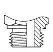
Installation of Tapered Port Fittings
When installing tapered fittings, the proper method is to utilize the ‘turns from finger tight’ method (T.F.F.T). Do not ever use torque settings for tapered fittings as many variables are involved especially when thread tape or sealant is used.
- Observe unassembled parts, especially threads and bore to ensure it is free of foreign material, burrs, nicks, etc.
- Apply thread sealant, tape or lubricant if not already applied. Do not cover the first 2 threads with any sealant or lubricant to avoid contaminating the system.
- If a thread seal tape is used, make sure it is wrapped 1.5 to 2 turns in a clockwise direction when looking at the bore of the fitting.
- Thread the tapered fitting into port until finger tight.
- Using the suggested T.F.F.T values in the chart provided, wrench the fitting into place.
- If the tapered fitting is an elbow, make sure the hose or tube end is oriented in the proper direction without having to loosen the fitting. Serious injury could occur if the fitting is loosened from its suggested T.F.F.T value.
- Inspect the final assembly for leaks. The number of threads engaged should range from 3.5 and 6.
BSPT T.F.F.T Values
| BSPT Dash Size | Inch Thread Size-TPI | Turns From Finger Tight (T.F.F.T) |
|---|---|---|
| 02 | 1/8-18 | 2 - 3 |
| 04 | 1/4-19 | 2 - 3 |
| 06 | 3/8-19 | 2 - 3 |
| 08 | 1/2-14 | 2 - 3 |
| 10 | 5/8-14 | 2 - 3 |
| 12 | 3/4-14 | 2 - 3 |
| 16 | 1-11.5 | 1.5 - 2.5 |
| 20 | 1-1/4-11.5 | 1.5 - 2.5 |
| 24 | 1-1/2-11.5 | 1.5 - 2.5 |

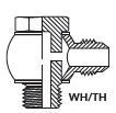
Installation of Female Swivel Fittings
- Observe unassembled parts, especially threads and bore to ensure it is free of foreign material, burrs, nicks, etc.
- Make sure the sealing surface angles are the same for the fittings you are connecting.
- If there is an O-ring located on one of the cone seats, inspect it for damage and replace if used or worn. Make sure O-ring is seated properly and not cocked or twisted.
- Never install an O-ring, bonded washer, or other seal at the base of the thread like you would a port fitting. Swivel fittings seal via internal surfaces.
- Thread and then tighten the swivel nut with a torque wrench while holding the corresponding fitting body with a wrench. Torque to recommended settings.
- If a crowsfoot is used with a torque wrench, adjustments might need to be made to the torque settings otherwise overtightening could occur. Consult your manufacturer for instructions.
- Inspect final assembly for leaks.

DIN DKO Swivel - Torque Settings
| Thread Size mm | Tube Size | DIN DKO Swivel (Nm) | |
|---|---|---|---|
| L Light Duty | 12 | L06 | 16 |
| 14 | L08 | 16 | |
| 16 | L10 | 26 | |
| 18 | L12 | 37 | |
| 22 | L15 | 47 | |
| 26 | L18 | 89 | |
| 30 | L22 | 116 | |
| 36 | L28 | 137 | |
| 45 | L35 | 226 | |
| 52 | L35 | 347 | |
| S Heavy Duty | 14 | S06 | 26 |
| 16 | S08 | 42 | |
| 18 | S10 | 53 | |
| 20 | S12 | 63 | |
| 22 | S14 | 79 | |
| 24 | S16 | 84 | |
| 30 | S20 | 126 | |
| 36 | S25 | 179 | |
| 42 | S30 | 263 | |
| 52 | S38 | 368 |
BSPP Swivel - Torque Settings
| Dash Thread Size | Inch Thread Size - Tpi | BSPP Swivel (Nm) |
|---|---|---|
| 02 | 1/8-18 | |
| 04 | 1/4-19 | 20 |
| 06 | 3/8-19 | 35 |
| 08 | 1/2-14 | 60 |
| 10 | 5/8-14 | 70 |
| 12 | 3/4-14 | 115 |
| 16 | 1-11.5 | 140 |
| 20 | 1-1/4-11.5 | 210 |
| 24 | 1-1/2-11.5 | 290 |
Please note:
- All torque values are intended for steel fittings.
- For Brass fittings and adapters use 65 % of the torque values.
- For Stainless steel fittings and adapters, use 5% higher value than listed and lubricate threads.
Installation of 24° DIN Tube Fittings
Make sure you fully read and understand the previous sections on DIN tube fittings and verify you have the correct components for your assembly.
- The first step is to cut the tube to length, then de-burr and clean. Cut tubing with appropriate saw only.
- Next, pre-set the cutting ring by initiating the bite into the tube. There are two ways to complete the pre-set: either a) manually with a fitting or hardened pre-assembly fitting body, or b) with a hydraulic pre-set machine. Hydraulic pre-setting is recommended for assemblies with tube size greater than 18mm.
- Perform pre-set inspection to verify proper installation of cutting ring.
- Install the assembly.
Manual Pre-set Method for 24° DIN Tube Fittings
- Lubricate threads of fitting and nut, 24° throat, and cutting ring.
- Place nut then cutting ring over tube, ensuring proper orientation.
- Thread nut onto fitting until finger tight. Press tube firmly into the tube receptacle of the fitting while doing so.
- Mark nut and tube position for reference with soap stone or marking pencil.
- Tighten nut so that it completes 1.5 turns (use markings as reference), while at the same time ensuring the tube is stationary and pressed firmly into the tube receptacle. Sudden resistance to torqueing is a sign the cutting ring is in a desired position. Be sure to secure fitting with wrench while tightening the nut.


Hydraulic Pre-set Method for 24° DIN Tube Fittings
There are various hydraulic pre-set machines available with specific instructions for each. Please refer to your user’s manual for operating instructions.
Pre-set Inspection
- Remove the nut from fitting and pull back in order to inspect the cutting ring.
- The cutting ring should leave no visible gap between the first cutting surface and the tube, and the tube should have a visible bite edge in front of the cutting ring (looks like slightly raised material).
- If not, tighten in small increments (checking the result after each increment) to verify cutting ring is properly gripping the tube.
It is possible for the ring to rotate around the tube, however this does not indicate an improper installation as long as all other factors are correct.
Final Installation
Take the pre-set assembly and insert tube into the fitting’s tube receptacle firmly, then tighten nut with light wrenching until resistance felt. Once this has been achieved, tighten the nut another 30° or 1/12th of a turn. This is the equivalent of turning the nut from a state where the hex is flat relative to a fixed point (i.e. a table) to where the sharp edge of the hex is now facing that position. Be sure to use a second wrench to hold the fitting in place while torqueing the nut.


")
How to order 24° DIN Tube Fittings from Adaptall
To order 24° DIN tube fittings from Adaptall it is important to understand the part numbering system. This system is typical of most manufacturers:
- The first four numbers indicate the part series i.e. 5000 is a male DIN union.
- The pressure class (LL, L, or S) is indicated at the end of the series number i.e. 5000L, 5002S, 5063LL, etc.
- For instances where a DIN x DIN fitting does not have a jump size, only one dash size is displayed. For example, a 5000L-06 is a light duty L06 x L06 DIN union.
- The dash numbers indicate tube size when describing the DIN side of the fitting. From the last example, a 5000L-06 is an L06 indicating a M12x1.5 thread with 6mm tube receptacle; see ‘Component Compatibility Chart’ on page 14 for details on tube size & thread size relationship.
- For non-DIN threads such as NPT, BSPP, etc., the regular dash system is used i.e. -08 indicates 1/2”, -12 is 3/4”, etc. Adaptall usually displays dash sizes with tube or hose side first, then port side.
- To order a complete DIN assembly (including fitting, cutting ring, and nut) simply add a “C” to the end of the part number. For example, a complete L06 male DIN union assembly would be 5000L-06C, etc. Please note that all LL series (extra light duty) parts come complete.
When a complete assembly is ordered from Adaptall, there is no need to identify components to go along with your assembly. Adaptall will complete the necessary steps to ensure you are provided with compatible components.
")
Example
Shown here in black only is 5158L-22-22-12: Male DIN X Male BSPP adjustable Run Tee, size L22 for the DIN threads, and dash size 12 BSPP (3/4”). When ordered as part number 5158L-22-22-12C it comes as a complete assembly with cutting rings and nuts for the two L22 Male DIN threads (components shown in green). Looking at the ‘Component Compatibility Chart’, one would notice the compatible nuts for this assembly would be 5201L-22 with the compatible cutting rings being 5202-22.